
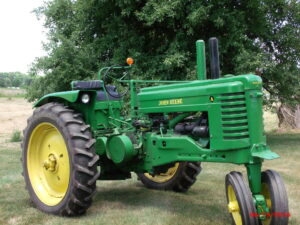
1949 John Deere “A” fender modification.
Although fenders were an option on this tractor, I think that they should have been standard equipment on any tractor of this vintage. The standard production fender (AA 1582 R & AA 1583 R) used on the 1938-1949 “A”, “B” and “G” is a good example. While these fenders add “curb appeal”, they also offer protection from a large and dangerous moving part.
Having had the production fenders on my tractor, I have a tendency to look at things on more recent tractors and wonder if that particular feature would enhance this older tractor. This habit has gotten me in trouble more than once in my lifetime!
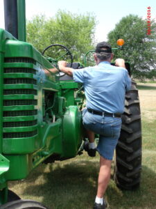
What I envisioned were fenders with a flat top and headlights similar in fashion to those found on the 30 series two-cylinder, and new generation row crop tractors. The cross section for this modification would be governed by the existing production fender, but the profile for the front part of this new fender would be similar to the new generation fender. A sealed beam headlight (AR 20443 R) would be placed under the leading edge of the fender to give better lighting. In addition, the left fender could be used to enable ingress and egress to the operator’s station from the front side of the axle, adjacent to the flywheel. Ingress and egress would require the installation of the grommet (R 20759 R) near the leading edge of the left fender and the placement of the step (A 5233 R) and its support bracket (A 5234 R) onto the front side of the left axle. Removing the production headlights from their existing location would provide even more room in this area.
A cardboard cross section of the production fender was used as a template to shape the new material for the front part of these fenders. Fourteen gauge sheet metal was the material of choice. Fabrication began by cutting into the cross section at its highest point and removing sufficient material on the front side of this section to allow the newly formed sheet metal to make a butt joint and be welded in place. Eleven gauge sheet metal was fitted then welded in place on the underside of the new fender near its leading edge, making this area more rigid and providing a place to secure the new head light. When the fabrication of each fender was complete, the fenders were mounted to their respective axles. The engine was then operated through its entire rpm range to test for harmonic fender vibrations. Only one very minor vibration occurred on the right fender at about 700 rpm. This was identical to the response of the production fender.
With the harmonic vibration test complete, the fenders were removed from the tractor and transported to Andrews Automotive in Mason, Michigan where the finish work and painting was done. Various areas of the fenders were covered with a product called Duraglas to fill imperfections and make a smoothed surface. Following the cosmetic work, both fenders were primed and then painted with John Deere paint (TY 25643). After completion of the painting process, the fenders were remounted to their respective axle. The headlight wiring was connected via a conduit (steel brake line) to a common source under the battery box. A final headlight alignment completed the project.
A pragmatic test was then preformed at night to evaluate the effectiveness of the new head light location and alignment. The result was very pleasing. Although it is an unconventional method for a tractor of this vintage, ingress and egress to and from the operator’s station is quick, easy and soon becomes quite routine.
Photos by
Sharla Piepkow
David Spragg
Holt, Michigan


