To some people, the words, “It can’t be done,” mean nothing more than “try harder.” I imagine that this was the motto of the mechanic who crafted this masterpiece of a conversion project. This John Deere “A,” originally an all-fuel model, has been skillfully converted to run on diesel fuel. If John Deere had sponsored this project, rather than a hobbyist near Owosso, Michigan, the model would likely have been called an “A-D.” While little is known about the man, now deceased, who completed this conversion project, his surviving relatives spoke highly of his mechanical skill at the estate sale where father-daughter team Dan Gingell and Rachel Gingell purchased the tractor. Dan Gingell, the tractor’s present owner, has reverse-engineered the tractor in order to determine how the fascinating conversion project was completed. The following is a step-by-step examination of the process.
Step 1: We start with a fuel injector, drilled into the engine head. The unknown mechanic selected a pencil injector, rather common in newer John Deere diesel engines, for its long, slim size. This injector, rather than a wider model, required a smaller hole with less chance of water leakage and damage to the valve guides. Dan Gingell suspects that the injector came from a 4020 series tractor, which was built during the 1970s and would indicate this conversion being completed sometime after 1980, when the part would have become more readily available.

Step 2: Of course, a diesel engine would have no need for a carburetor. This picture shows how the carburetor was replaced with a custom-cut pipe, allowing the intake manifold to get air even though the carburetor is removed from the design. Fuel lines which would normally come to the carburetor have also been rerouted.

Step 3: Our mystery mechanic drilled a hole in the block directly behind the spark plug and added a special oil line. This line sprays oil on the piston rings, sealing them and improving compression. The old spark plug hole was plugged and tightly sealed.

Step 4: The oil for these lines comes from the back of the governor housing, pictured here. A “T” was inserted in the line leading to the oil pressure gauge, diverting some of the oil to spray the piston rings. A nice cycle is created—oil on the rings drips down the block and runs back into the regular oil system, with very little impact on oil pressure or consumption.

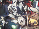
Step 5: Pictured here is the fuel pump, one of the most ingenious parts of the tractor’s design. While the distributor would normally be bolted on to the governor housing in the upper left of this photo, it has been removed. A gear and chain system, coming from the distributor drive, powers the fuel pump. The pump is a Bosch four cylinder design, likely removed from a small diesel engine. It is not a popular pump for tractors, but it works incredibly well here in the “A.”

Step 6: This picture shows the custom-built manifold coming off the side of the fuel pump. As you can see, the pump is designed for a four cylinder engine. This custom manifold allows for each cylinder to get two pumps of fuel for every compression stroke of the piston. While this may seem like a significant amount of over-fueling, it is necessary to get enough compression. Using a four cylinder injector to feed a two cylinder engine is the key to this design.

Step 7: Before the fuel enters the fuel injector, it passes through this smartly designed fuel filter. Copper lines bypass the regular system, which would send fuel to the carburetor, and instead feed directly from the filter into the injector pump.

It may appear that the mechanic who designed this tractor has taken his secrets to the grave. However, by closely examining and studying the tractor we have figured out many of the secrets. The tractor runs surprisingly well and has an interesting sound. To watch a video of the running tractor, visit www.FarmTractorRepair.com.
Submitted by,
Rachel Gingell


