
Unstyled JD “HNH” – Conceived October 2006, built 2007
It’s no “OX”
By Patrick Browning
The idea: If John Deere were to have built an unstyled model “H” tractor in 1935, this was to be the tractor Deere would have built.
The concept: “New Johnny,” as it soon would be named, was to begin with a working JD “H” tractor, serial number 10,000 or higher, the front parts from an early unstyled JD “B” tractor plus (perhaps) some wheel parts from various tractors if needed.
Since narrow front and higher crop clearance would be even more rare, conceived final construction would have a single yoked wheel up front and 38 inch rears. The unstyled JD “B” pedestal would be remanufactured to accept a vertical spindle shaft with yoke from a “BN” tractor to convert to a typical Hi-Crop configuration to fit the JD “H” chassis.
Engineering and design: The result was to be a new tractor, but of vintage 1935. The new tractor must appear to be one that could have come from a Deere factory. Design criteria called for a “finished” look in all areas. Some liberties would be taken, but in general, even the decals would be selected to date this tractor as a vintage 1935 JD “HNH.”

Starting point: Since the relationship between fanshaft and governor on any JD tractor is very delicate, this was the place to begin. The radiator chosen was from a 1935 JD “B” and to accommodate the lower tank required widening of the front end support (FES). In determining the radiator’s forward and aft location, the distance between fan and radiator core was held to the same as for the JD “H.” Shimming between radiator and FES for elevation plus radiator mount centering would align the JD “H” fan and fan shroud. Another observation at this point was to ensure sufficient clearance for the steering (worm) shaft above the upper radiator tank in preparing the drawings to remanufacture the FES.

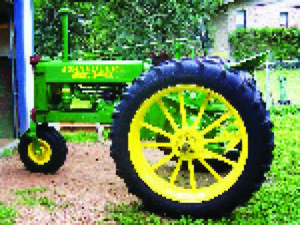
Rear wheels: One early-on decision was that this tractor would have 10-38 rears with 12 spokes—38 inch to provide the Hi-Crop property and spokes of 3/8 by 1-1/2 inch bar stock common to the mid ’30s era. These wheels would be designed and built to mount onto the JD “H” seven-stud rear wheel hub.
Hood and tank versus engine utilities: With both JD “B” hoods on hand (long and short), it didn’t take long to settle on the short hood version. During the ensuing weeks, there would be a boat-load of fit-checks using this hood and tank assembly along with radiator, fanshaft and governor housing in place. Major tasks included redesigning and rebuilding the air filtering system, relocating and/or rerouting for the upper water pipe, exhaust pipe, tappet breather pipe and fuel filter along with new fuel lines. The other two biggies were designing a rear tank support and mounting the gauges for water temperature and oil pressure. Meanwhile, a search for parts for the front end continued.

Air cleaner and air inlet: Interference with the fuel tank was the driver here! The JD “H” air cleaner canister was modified and adapted to the JD “B” casting that forms the interface between canister and upper radiator tank and outfitted with a special 90 degree elbow aimed in the center of the scant amount of space between tank and canister. To facilitate connection from canister to carburetor, the JD “H” air inlet elbow was modified; its upper 90 degree bend was removed to facilitate a straight-up hose connection into the air canister’s new special elbow. All that remained once these hurdles were crossed was to install a “slice” between the carburetor and air inlet elbow. An earlier design of a modified B1408R air inlet elbow was attempted but drawing tolerances proved too wide and the fabricated result failed. Thus the need for the “slice.”

Upper water pipe and breather pipe: The upper water pipe from the “H” tractor needed to be lowered to make room for the fuel tank and steered to the left, toward center, to align with its mate from the upper tank. Once this re-fabrication was completed, the breather pipe now failed fit-check and also needed some tweaking. It was cut, an insert installed and re-bonded to aim in a new direction just between fan shaft and upper water pipe!
Muffler and exhaust pipe: At the manifold is a two-bolt flange with donut seal for 1-1/2 inch OD pipe (flared), while the other end fits into the “H” muffler. A JD “B” muffler was intended for use, but pipe stock to fit could not be found. Accordingly, the “H” muffler was used, its mounting hole footprint modified to fit the upper radiator tank mounting, along with a 5/8-inch thick shim between muffler and tank to position the muffler to match the exhaust exit hole in the hood.
Fuel filter location, fuel lines: Next up was placement of the fuel filter. At issue here was interference between fuel filter and fanshaft and interference between fuel lines and manifold as well as achieving a design appealing to the eye. Searches included special fittings as well as other models of fuel filter in an attempt to use the fuel tank as is. The final outcome, however, involved moving the fuel filter back three inches and out from center by an inch. The three-way fuel valve is one from an early “B” tractor and has performed flawlessly. New fuel lines were built for this tractor using all new parts, resulting in no leaks!

Rear tank support and plug wire conduit: During all prior activity, eyes were always on the rear tank support. On the “B” tractor, the governor hosts the rear bracket. For the “H,” the cylinder block is the rear tank support point. But for this application, neither held great promise and a rest on the fanshaft was undesirable! Several prototypes were built, and on a third trial, the resultant scheme was found. It was a totally new concept! The pressed steel crankcase cover would go away, replaced by a cover made of 1/4-inch thick steel and atop this cover would be attached a U-shaped bracket to mate with a the “B” rear tank support with the U-shaped piece designed to come around the fanshaft. Meanwhile, the design was conceived to modify the “H” rear tank support bracket to hold the sparkplug wire conduit in place.
Gauges mounting bracket: As with other designs, prototypes of various mounting brackets were constructed. The final design places a gauge on each end of a “bow tie” shaped bracket. The bow tie is saddle-blocked and bolted to the steering shaft support pipe. Interconnection lines traverse from there, dressed over the top of the governor-magneto region.
Main tractor build-up: While design (drawings), fabrication, fit-checks and trials were carried out for the changed parts, restoration of the engine, clutch, transmission, rear axle assemblies plus installation of PTO were being accomplished. This tractor has a new engine with a freshly turned crankshaft and mating rods donated by Russ at Paul’s Rod and Bearing; the rods also mated to new oversized domed aluminum pistons, both pistons and block over-bored to a matching 0.040-inch over standard bore. The head was given new life as well to include a total valve job plus all new valve guides. Surface milling was also a normal part of the job for the head, block and manifold to ensure flatness.
All bearings and bushings were renewed. We even have new “dog bones” in the clutch! The cam gear, reduction gear and sliding shaft plus two other gears were replaced with serviceable ones. The cam gear and reduction gear were lost because they were not tight on their shafts. I was blessed on the camshaft; the replacement gear locked on well. All new bearings included the governor and fanshaft (no fun). The carburetor was done by the book and a new magneto was installed. As is my style, all individual parts were painted with John Deere green paint prior to installation as are also each fastener. This goes a long way to ensure no voids after the tractor’s final paint shoot.
Pedestal, spindle with yoke and front wheel: Finding a “BN” pedestal is tough. The plan all along was to cut off the lower extension of a regular early JD “B” pedestal and install a suitable thrust bearing or bushing for the spindle with yoke. In my search for front end parts, I did manage to find Bob Lovegrove with some key parts on hand, mainly a vertical spindle with yoke from an early JD “BN” plus a front wheel with new tire to match—a 6.50 x 10 tri-rib tire. It appeared we were moving in the right direction.

Thrust bushing (B545R): With spindle shaft on hand, the B545R bushing was the one chosen. Finding a replacement thrust bushing proved interesting indeed. Besides Deere, numerous NOS sources were tapped to no avail. One of the Restoration Guide’s co-authors pointed me to Don Selle of Turtle Lake, Wisconsin as a source. Don wasn’t sure, but said he would do some scouting around.
During what was probably the coldest days of the 2006-2007 winter season, Don called me to see if I still needed the bushing. “Yes,” I told him, and so he set the wheels in motion. It seemed that a man he knew was willing to extract a B545R bushing from an existing BN tractor, send it to Don, who in turn would machine some salvaged Caterpillar bushings into B545R bushings, then return the original. The deed was done and I received the bushing at a fair price. Here’s the best part: The man loaning the “pattern” bushing was none other than Bob Lovegrove! As with Russ at Paul’s Rod & Bearing, small world! Great men!
Now with bushing in hand along with the spindle with yoke assembly, drawings were completed and released along with the parts to a fabricator/machinist where they sat until the end of my patience. It was time, I thought, to get the job started. I visited the machinist. He promptly cut the lower part of the pedestal per my drawing.
Surprise! Surprise! Lo and behold, the casting’s inside was shaped differently from what I envisioned. It was larger and irregular! It is time for a sleeve and perhaps a huge Bridgeport Machine to prepare the casting for the sleeve!
We did no more that day. The job was left in the machinist’s hands. Two more months passed without action. When pressed, the machinist reluctantly but with relief, admitted he was “out of airspeed and ideas.”
I picked up the parts and bought special grinding tools. By hand, I carefully machined that casting to accept a sleeve made from DOM pipe. The sleeve was sized and reamed to accept the B545R thrust bushing and special tooling was acquired to ensure fullest alignment of the sleeve as it was being welded in place. With thrust bushing pressed and bonded into place, the next fit check was an on-tractor installation of pedestal with spindle, yoke and tire. New Johnny was finally on its own feet, started and backed out of the shed. The front of the tractor was too low! New Johnny looked more like a puller than a farm tractor. Recall basic criteria that this was to appear as one Deere could have (and would have) built in a factory. A tractor pull back in 1935 was generally of a plow or disk out in the field, surely not for show at the county fair!
The solution was to lengthen the fork tines of the yoke by an inch and go to a 9.00 by 10 tri-rib tire in place of the 6.50 by 10. The change provided just over 2-1/2 inches rise of the front end and the result was right. One final fit check to test turning exposed interference between the weldment atop the yoke and the FES. This issue was solved by grinding the weldment height down to provide the needed clearance.
Pat Browning died a few years back, but if you know where his creation now resides, we’d love to hear about it.


